5 minutes
CNC Gantry Deflection
A few weeks ago, I was testing drilling holes in aluminum on my CNC and broke a bit. I’m not going to go into what went wrong here to make the bit break; that’s not the important part right now. What matters is understanding just how much force can be involved in milling, even with a light-duty CNC router like mine. Here’s the video:
One of the fascinating things (to me, at least) was how much the CNC’s gantry moved. If you watch, in addition to seeing the vise shift, you can see the gantry deflect upwards a bit. Not a lot, but I don’t want to see my CNC bend under load.
I’m not an real engineer (no matter what my business cards say), but back-of-the-envelope deflection math is fairly easy. Deflection varies as the square of the unsupported length and as the inverse of the third power of the height of the beam. So, if the gantry is twice as long, then it’ll deflect 4x as far under the same load. Or, if the gantry is 2x as tall, then it’ll deflect 1/8th as much. If you want less deflection, then make it taller with shorter spans. Simple, right?
Since I have a 1,500mm long gantry, I’m going to have way more deflection than people with a smaller CNC.
The Beaver HDZero’s gantry is made out a pair of 40x80mm aluminum extrusions, which are fairly strong. Due to the way they’re used, the 40mm side gets to deal with the vertical load on the system, not the 80mm side. I was curious how bad the deflection problem was, and if there was anything simple that I could do to improve it.
First, I wanted to measure how bad the gantry deflected. To do this, I attached a dial indicator on an indicator holder to my CNC, and then used that to measure the distance between specific locations and the CNC’s base plate. I actually milled a threaded M5 screw hole into my spindle mounting plate just for this sort of use. I unscrewed the indicator holder’s arm from its magnetic base and screwed it right into the mounting plate. That way it moves up and down with the Z axis of the CNC. By adjusting it carefully, I can get extremely precise and repeatable measurements.
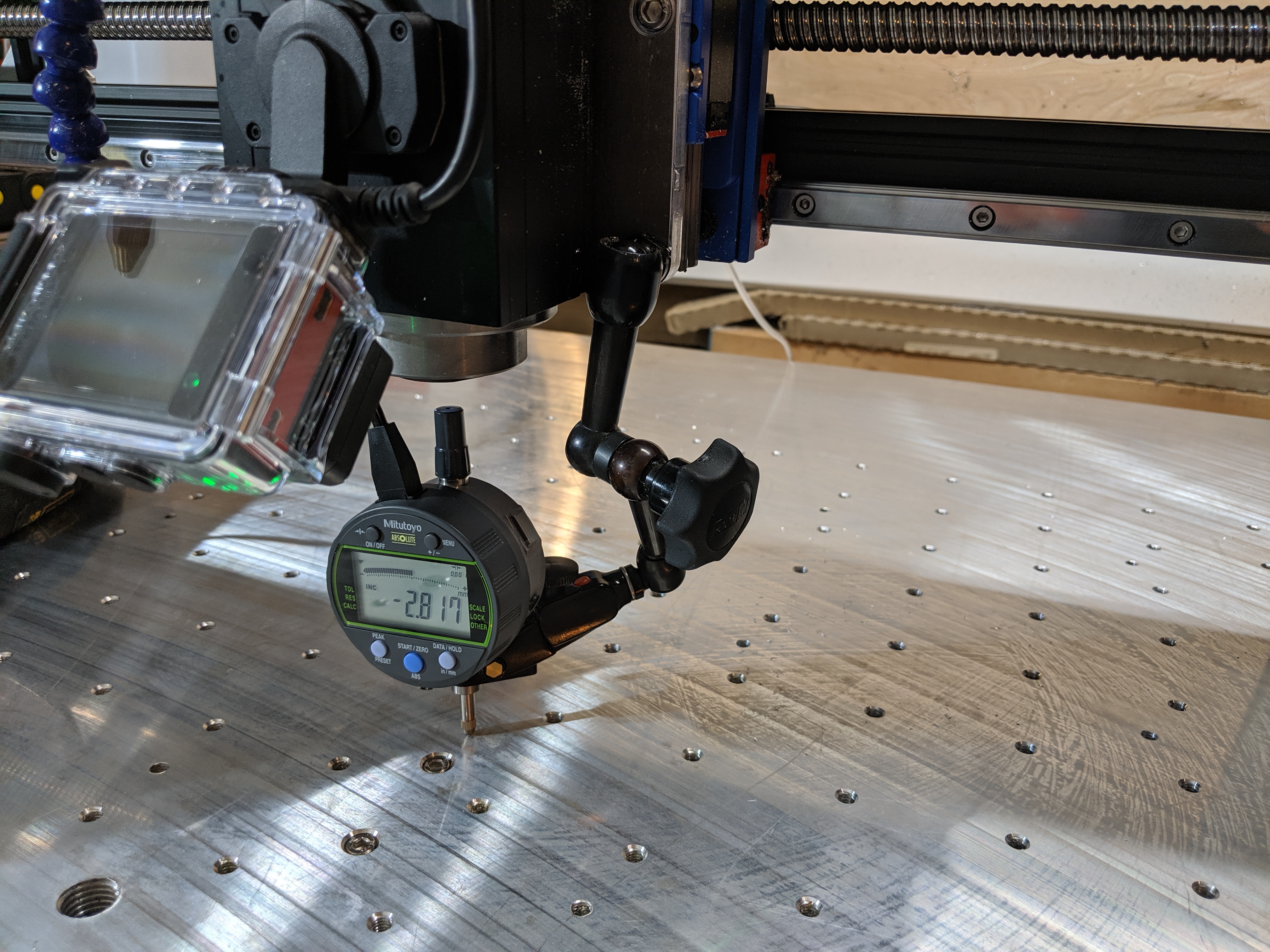
How precise? I’m using a Mitutoyo 543-302b digital dial indicator which displays 1 micron increments and is supposed to be repeatable to 2-3 microns. I was generally able to get results repeatable to within 3 or 4 microns, even after moving my CNC around. Considering that a single stepper motor step on my CNC’s Z axis is around 6 microns, that’s much better than I’d expected.
My first test was simply to move the CNC to the middle of its range and measure its deflection both with and without a known mass. I used a 5lb weight bag that I had handy. With no weight the dial indicator read -2.202mm. Adding 5 lb to the gantry right next to the Z axis increased that to -2.263mm. That’s 0.061mm, or 61 microns of deflection. I probably should have just declared that to be good enough–I’m mostly planning on milling wood, and that’s good enough for wood. Wikipedia says that 70 microns is usually used as the width of a human hair for comparison purposes, so it’s less than a hair’s worth of deflection. In imperial units, it’s around 2.4 thousandths of an inch–some, but not a ton. It’d be kinda nice to be able to be under 1 thou. So I continued.
I measured the deflection along the X asis every 50mm, starting at the
center of the span and heading to the edge of the CNC. To do this, I
measured the offset at 14 points without the 5 lb weight, and then
re-measured each with the weight. At first I did this manually,
typing g0 x-200 a lot, but eventually I automated it but putting all
of the move commands into a file and using a USB cable to grab
measurements directly into a spreadsheet. Once that was set up, I ran
each test 3 times back-to-back to minimize error. The median error
across sets of 3 samples was only 3 microns.
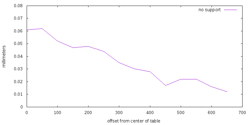
That looks roughly like what I’d expect. Deflection is greatest in the middle of the table (at the left here) and drops off dramatically towards the edges.
Next, I tried adding some bracing. The top and bottom rails on the gantry are 56mm apart, so I bought a few 55mm 20x20 extrusions and some corner brackets to use to connect them. They’re not perfect, but they’re easy to add and I figured I could see if they made any measurable improvement.
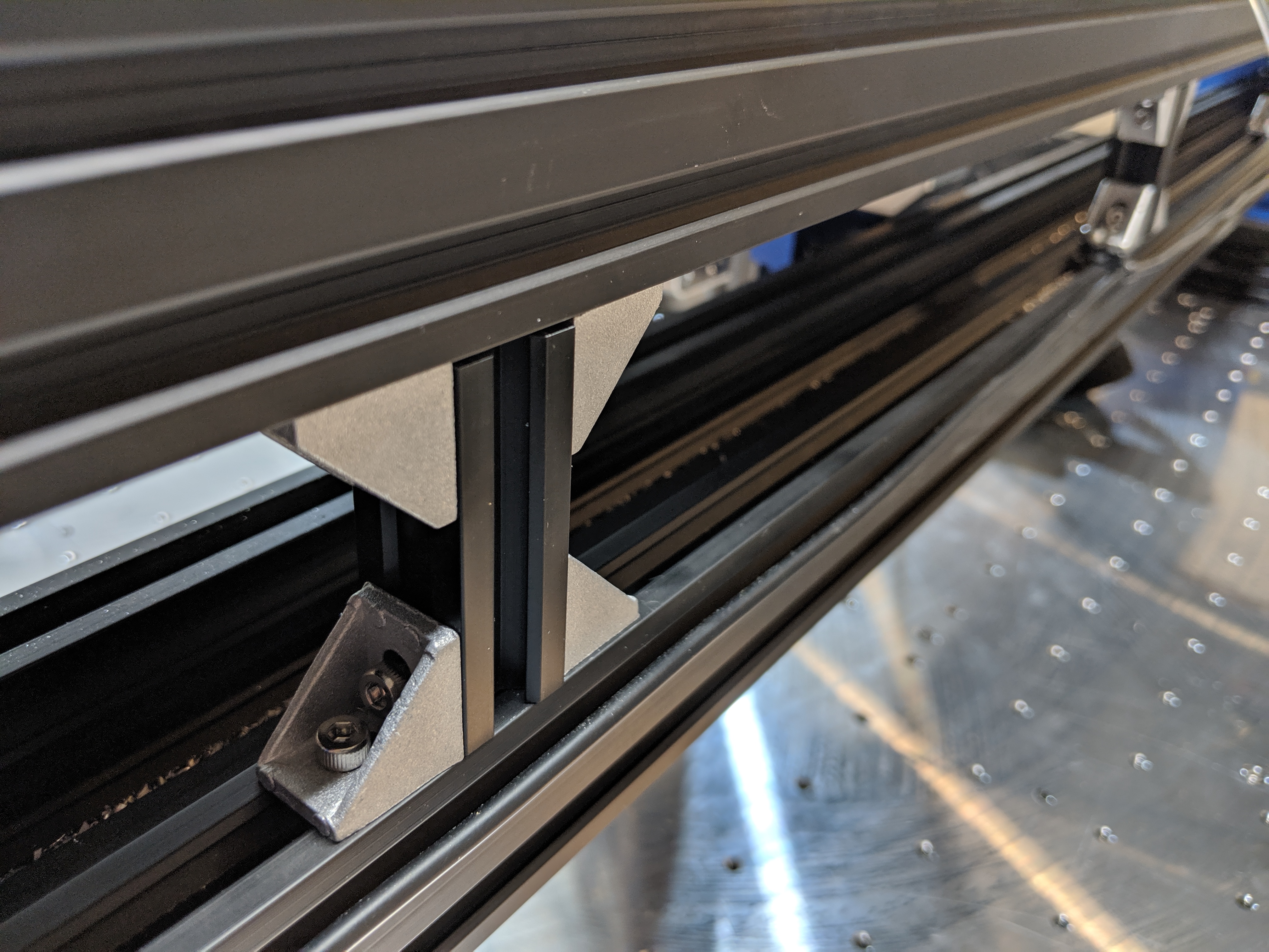
Here’s what I measured with 3 of them installed, evenly spaced across the span:
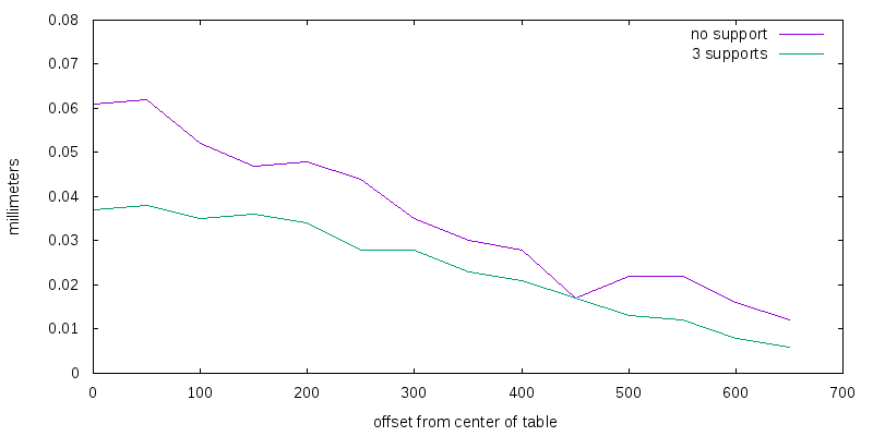
That seems to have reduced the deflection by 1/3rd. I don’t think I have enough M4x8 screws to try 7 braces, but I suspect it’d be a small improvement over 3.
I’m also curious if the added bracing improves surface finish at all. Unfortunately, I don’t know how to measure that objectively on a budget.
Update: I realized that the 3 micron repeatability is a probably a function of the closed-loop steppers that I’m using. The way the Z-axis stepper is configured, it’s only good for 6.25 microns per pulse. That is, the smallest step that the controller can tell the motor to make results in the Z axis moving 0.00625mm. But, it’s clearly able to consistently return to the same locations within 0.003mm, even after moving a long ways.
The answer is almost certainly the encoder attached to the stepper motor. The encoder has a resolution of 1,000 lines per rotation; at a minimum that’d be 5 microns on the Z axis. I’m not an expert on encoders by any stretch, but Leadshine says that this motor/driver/encoder combo should be set for an encoder resolution of “4000”; assuming that’s measurable levels per rotation, that’d give us 1.25 microns of precision. In any case, the encoder should make the stepper be repeatable to within 5 / 2.5 / 1.25 microns, no matter what the pulse step size is set to.